Groundworks: drainage and the heat pump ground collector

In addition to digging the house’s foundations we needed groundwork undertaken for foul and surface water drainage and for the ground array (heat collector pipe) for a ground source heat pump. We describe these works later in this section.
Surface Water Drainage
Our site is near the bottom of a valley and the ground consists of soft and stiff clays. Whilst not in a flood zone (a point we checked before our first visit to the site) surface water drainage had been somewhat of a problem and flash flooding has occurred on a couple of occasions in the previous 20 or so years associated with prolonged heavy rain onto saturated ground (flash flooding can also occur with heavy rain on very dry ground, after a drought, for example).
In addition to the new surface water drainage we installed we were also supported by the local planning authority agreeing to raising the finished floor level of the house by 167mm over that of the previously-planned property to further reduce the risk of water ingress into the house itself.
The picture below shows flash flooding in 1998 in front of the original bungalow and across the bridlepath. (As referred to later in this post, we installed a drainage gully adjacent to the bridlepath (on the right of this picture) to help with surface water drainage to reduce the risk of a recurrence of this problem. Subsequent prolonged heavy rain onto saturated ground, when there was severe flooding in parts of Herefordshire and Worcestershire, has shown that not only the gully performs well but the overall surface water drainage system has kept hard surfaces clear of standing water and reduced the usual winter bogginess of the fields in the immediate area.

Flash flooding across bridle path in front of the original bungalow on our building plot
The plan below, dating back some 30-40 years, shows long-standing (probably Victorian) clayware drainage pipes running roughly west to east and a newer plastic drain put diagonally across the lower field (running roughly south-west to north-east). Whilst much of the new surface water drainage pipes we laid bypassed these it was necessary to repair some of the original Victorian drains (which were still working) and to connect drainage pipes laid in the previous 50 years or so to the new system. This has improved the surface water drainage of the surrounding area and, we hope, further reduced the risk of flash flooding.
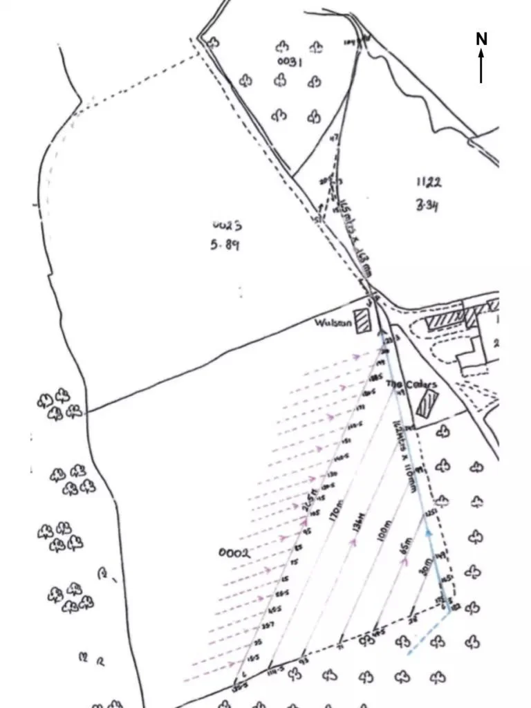
Plan of original clayware field drainage pipes and a newer plastic one cutting diagonally across the field connecting, via more clayware pipes, to the brook (shown at the top of the plan)
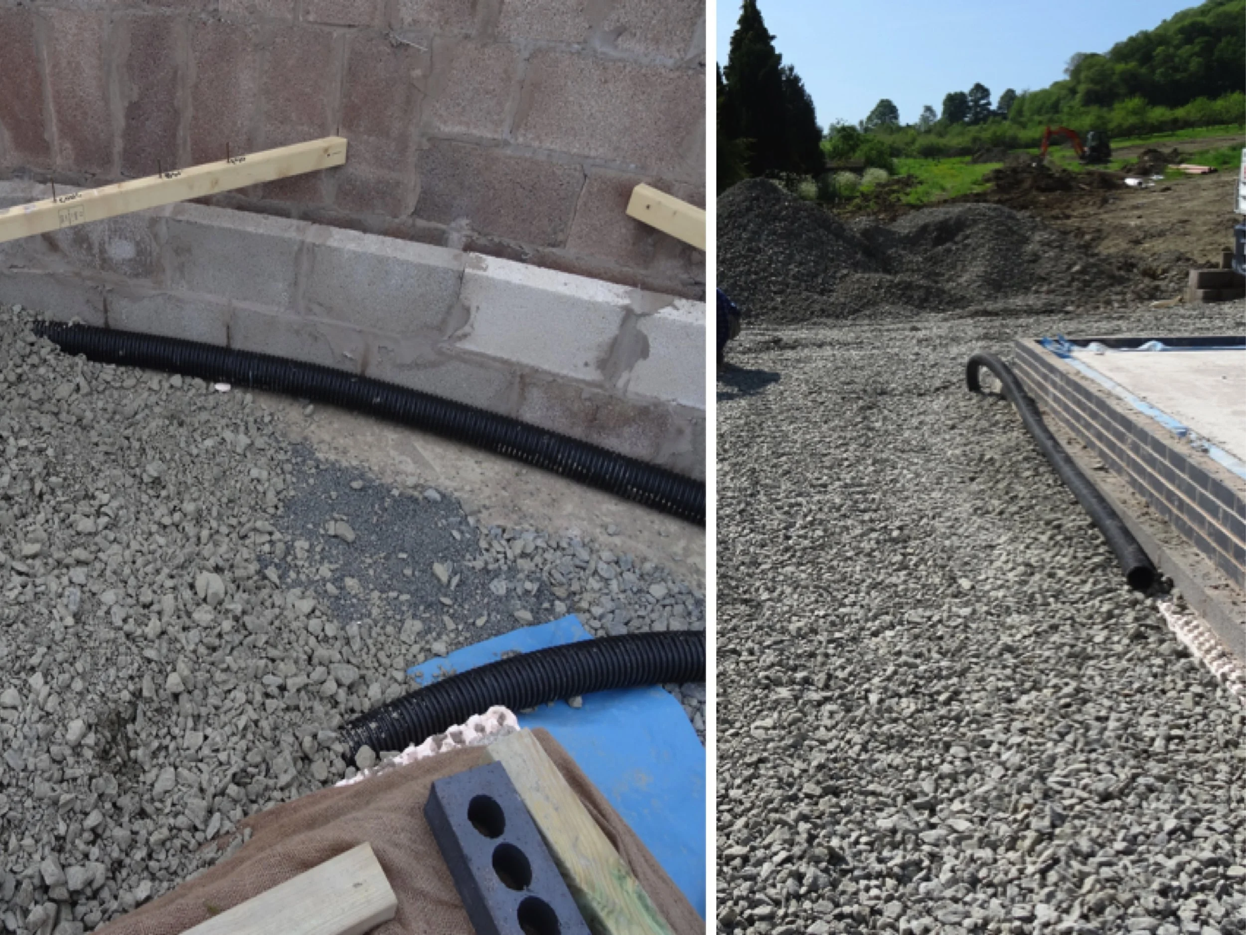
Crushed stone under the house’s foundations, and perforated drainage pipes around the house and retaining walls are a main part of our sustainable drainage strategy
The pictures above show additional surface water drainage pipes laid around house foundations and the ‘horseshoe’ retaining wall to be connected to the new surface water drainage system to reduce the risk of flash flooding. The stone around the foundations is also part of a sustainable drainage system (SuDS) to collect water via a fin drain also connected to the pipe run going to the brook in the valley floor. The ones below show some of the, presumed Victorian, drains and some of the new drainage pipes.
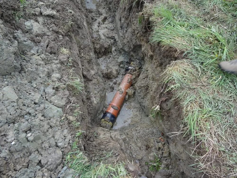
A more-modern cylindrical clayware drainage pipe exposed during groundworks that needed connecting to the new surface water drainage system
Repair to a clayware drainage pipe exposed during trenching for the French drain going to the brook in the valley floor
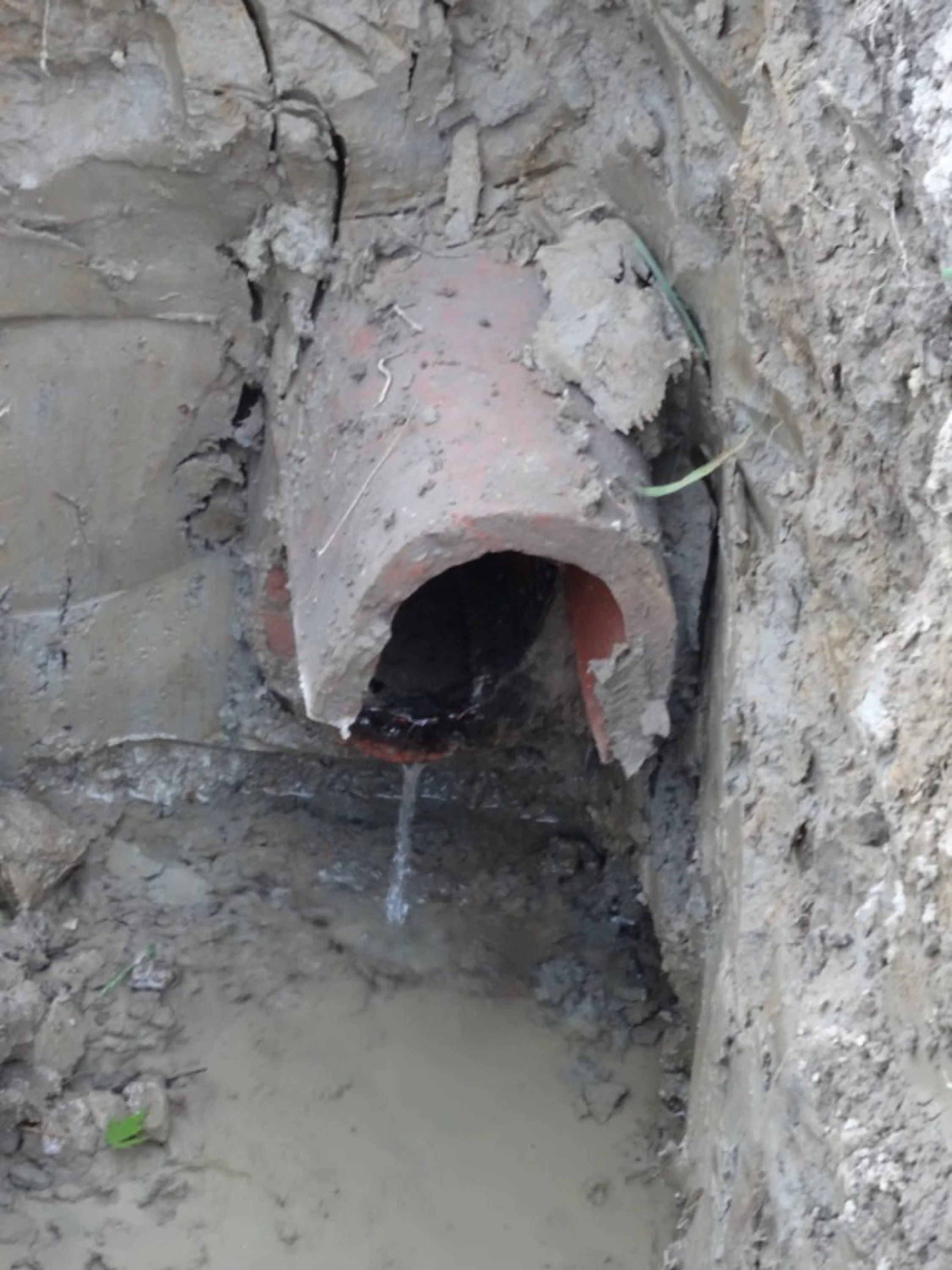
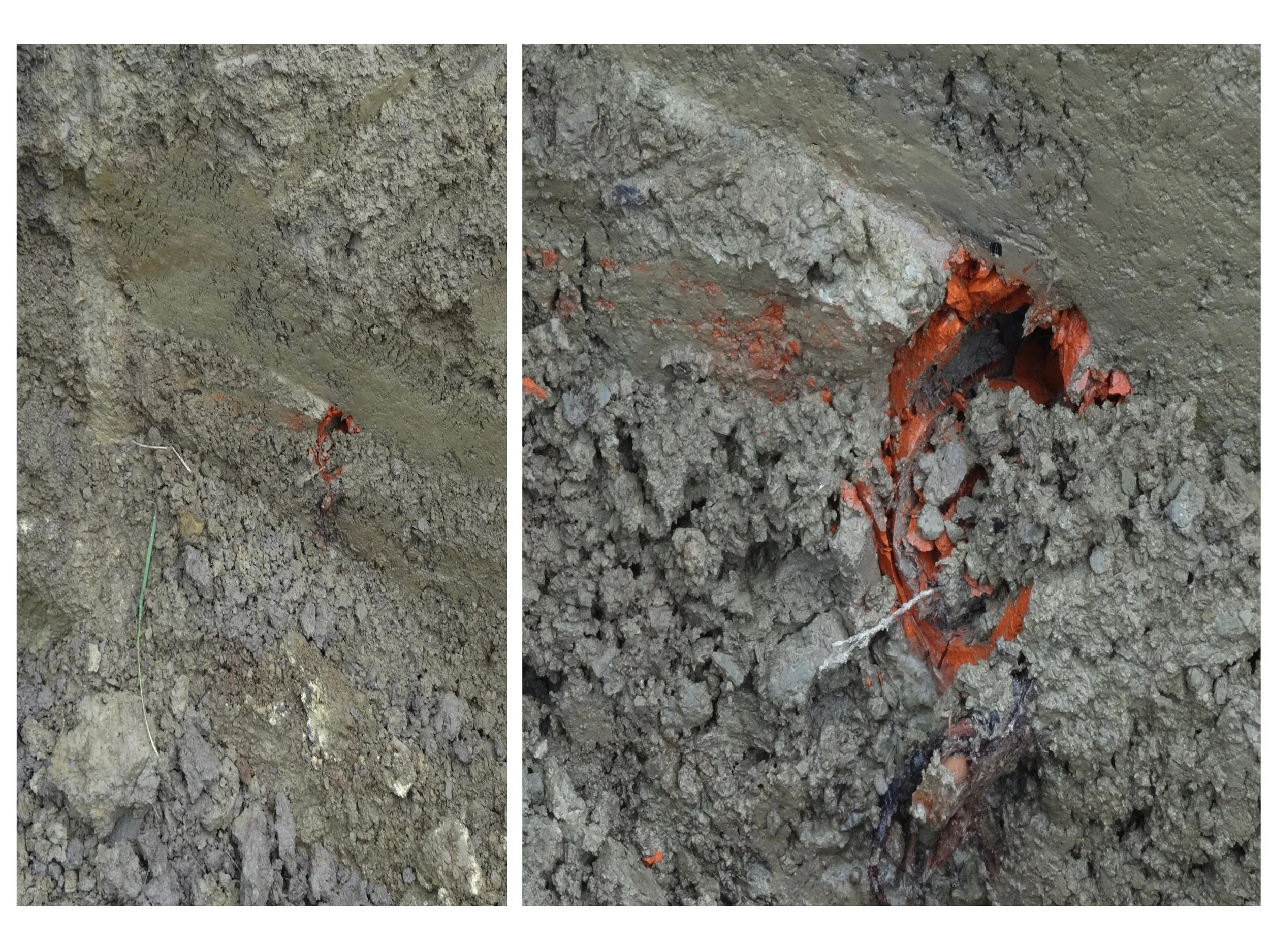
A U-shaped (or horseshoe) clayware surface water drain, probably Victorian, exposed during trenching that required repair (shown in the next picture). The upper and lower U-shaped ’tiles’ are visible as is water coming out of the lower portion: this system is still functional. In at least two areas in neighbours’ fields these pipes had collapsed causing small sink holes requiring repair to reinstate the drainage function and for safety
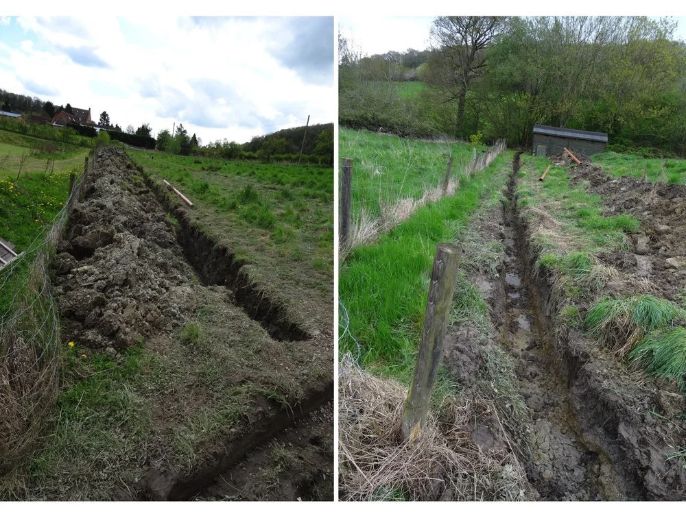
Left, a trench across a neighbour’s field for a French drain and for a separate non-perforated pipe taking the outflow from our sewage treatment plant towards the brook in the valley floor. On the right, the final pipe run trench to the brook through a second neighbour’s field
The picture on the right shows the connection between the pipes laid in the two trenches in the two pictures above right. The Y-junction (bottom right of the photograph) is taking the two pipes laid in the trench shown in the left of the two pictures above right. The single pipe leaving it is unperforated and provides a straight run to the outflow into the brook in the valley floor (running in the trench in the extreme right-hand picture above.
All the drainage pipes were laid on, and then covered in, pea gravel to provide protection against ground heave and to further facilitate ground water drainage (as shown in the picture below). The pea gravel was placed directly on to unperforated pipes whilst the perforated pipes were enveloped in a geotextile permeable membrane before pea gravel was placed on top to prevent ingress of soil particles and vegetation roots (as shown in the photograph below).
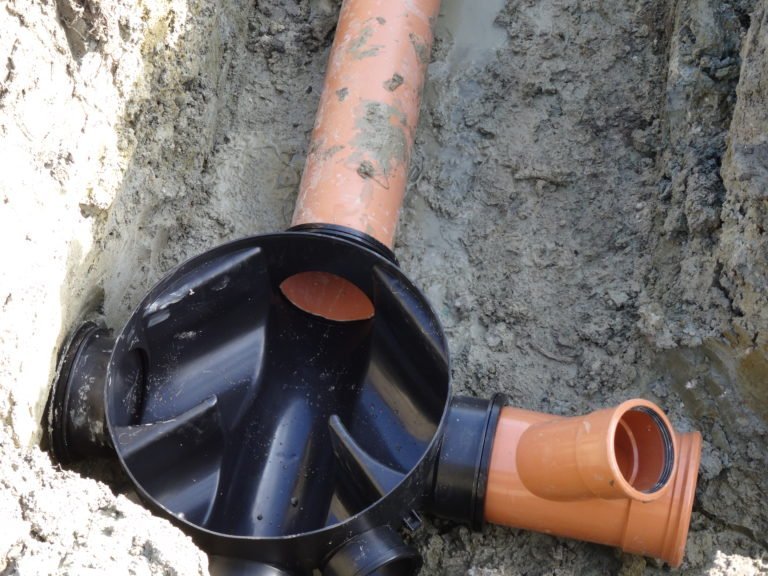
Lower part of inspection chamber (black plastic) between pipe runs in one neighbour’s field and the final run to the brook through another neighbour’s field. This is also the point where the French drain (providing surface water drainage to benefit both neighbours and, hopefully, improving overall land drainage in the area), and the hitherto separate pipe carrying the outflow from our sewage treatment plant, are combined at the brown plastic Y-junction visible on the right of the picture

French drain with perforated pipe surrounded by a non-woven geotextile permeable membrane prior to final covering with pea shingle. This allows water drainage but prevents ingress of soil particles and vegetation roots into the drainage system. Two pipes are visible: the lower is the perforated land drainage pipe and the upper an unperforated one carrying the sewage treatment plant outflow
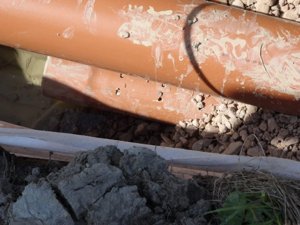
Close-up of the two pipes shown in the previous picture. The upper, unperforated, one carries the sewage treatment plant outflow and the lower, perforated, one is for land drainage. The perforations are only on its upper surface so water in it can easily flow to the outfall and not seep back into the ground

Outlet into the brook in the valley floor constructed of concrete-filled bags
Finally, to help with surface water drainage on the road immediately outside the property, we installed a road gulley and connected this to the pipework going to the brook. It replaced an existing concrete slab arrangement that, to some limited extent, provided a similar function.
We later inserted a silt bucket into the trap beneath this gulley to make it easier to clear out debris and reduce the risk of the drains becoming blocked.
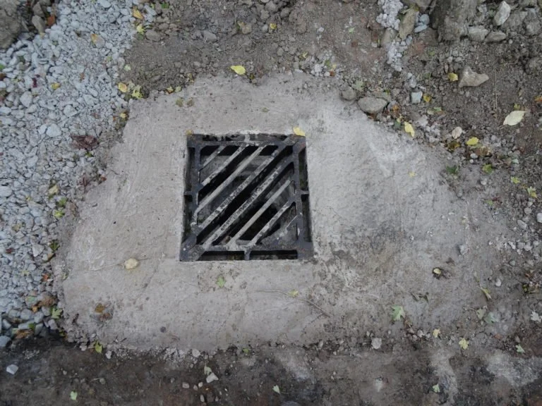
New road gully and piping to substantially enhance surface water draining from bridle path and reduce flash flooding risk
2. Foul water drainage
Being in a rural location, we are not connected to a main sewer so it was necessary to install a ‘compact’ or ‘package’ domestic sewage treatment plant to render outflowing water from the house from the sinks, bath, showers and toilets suitable for discharge into a watercourse. (Rainwater from the gutters and all surface water bypasses the sewage treatment plant.) And a note if you are considering a building plot with an existing cess pit or septic tank: the law changed in 2020 requiring their replacement with a sewage treatment plant.
The Conder ASP sewage treatment plant
One problem we had was our desire to also have a water softener for the house: whilst most water softener suppliers say that their systems can be used with sewage treatment plants, most sewage treatment plant suppliers say this is not the case.
The issue is that the regeneration cycle of a water softener dumps a relatively large amount of salt into the house’s wastewater every now and then. Some suggest that this might be deleterious to the bacteria that break down the contents of the house’s foul water outflow in the sewage treatment plant. It is this bacterial process that renders the sewage treatment plant outflow safe for discharge into the environment. Most of the research on this subject that we could find was undertaken in the USA and mainly concerned septic tanks rather than sewage treatment plants (which work differently) or had been undertaken only in a laboratory setting. The other problem we found was that much of the internet content on this subject is to be found in various system suppliers’ sites so it was not necessarily completely bias-free.
However, after a lot of research, we came up with a couple of suppliers, one of which, Conder ASP (now Rewatec ASP), stated in its literature (and confirmed in emails to us) that its package sewage treatment plant was, indeed, fine for use with domestic water softeners albeit not those on commercial premises.
The photograph on the right shows that ‘compact’ sewage treatment plants are not as small as their name might imply (this one is designed for up to six people’s regular use). They need a big hole in the ground and sit on a shingle base with a concrete ‘collar’ to keep the plant in place. An unperforated, drainage pipe takes the clean outflow away.
And, after a similar amount of searching, we found the Ecowater Refiner 500 water softener which is said to regenerate ‘little and often’, that is, to put out relatively small amounts of salt in the regenerant water frequently rather than infrequent large slugs, which should be less of a shock for all those bacteria busily digesting the unspeakable contents of the sewage treatment plant. Our problem-free experience over more than three years is that our Ecowater Refiner 500 water softener works well with our Condor ASP sewage treatment plant.
3. Installing the ground array (collector) for the ground source heat pump
The final piece of major groundworks (other than landscaping) was the installation of a ground loop collector for our ground-source heat pump. We discuss ground-source heat pumps in another post, but suffice to say here that for this we needed a trench that was 125 metres long, one metre wide and just over one metre deep. It made sense to dig this whilst having the digging equipment on site for the drainage and other ground work. We sited the heat pump ground array trench towards the bottom of the field next to the French drain adjacent to another neighbour’s garden, as shown in the pictures below.
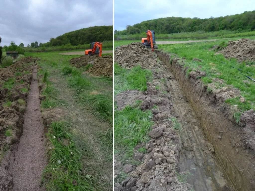
The pictures above and below show the trench being dug for the ground source heat pump array. On the right below, looking back towards where the house will be, it’s clear that the ground is wet: this helps considerably in transferring heat from the ground into the fluid circulating in the heat pump ground array pipe.
The pea gravel-filled French drain adjacent to a neighbour’s garden is shown in the left-hand picture above, and, slightly uphill from it, the trench for the ground-source heat pump collector pipe is being dug, also shown in the right-hand picture. An advantage of this positioning is that it encourages a flow of water across much of the length of the ground loop thus aiding the transference of heat from the higher ground where it is heated by the sun (wet ground transfers heat more effectively than dry; the most efficient transfer being achieved with a heat collection array in water such as in a lake).

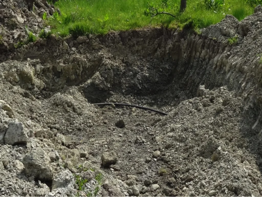
Ground-source heat pump collector pipe looping round at the far end of the trench for its return run to the house 125m away
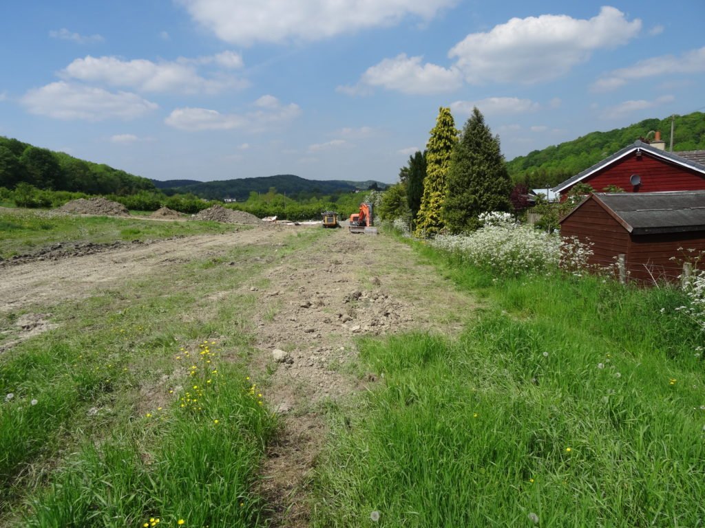
View towards building plot showing covered-over surface water drain (on the right of the picture) and the ground-source heat pump collector loop (on the left). With final levelling and the grass regrowing, these rapidly became invisible