Raising the oak frame and installing the encapsulation system
Here we briefly describe designing the oak frame, but mostly concentrate on Oakwrights raising it and installing their encapsulation system after Furber Young Developments Ltd. had prepared the foundation slab. There are links in this post to videos of various aspects of the process.
Designing the oak frame
Having worked with the Oakwrights architectural designer/passive house consultant on the overall design of our house an Oakwrights frame designer worked with us to explore oak frame options. This included thinking about the location of windows, kitchen cabinets and the like to ensure that, for example, there wasn’t a beam or brace covering a window. When completed, the frame design was checked by an Oakwrights structural engineer. The final design of the oak frame is shown in the diagrams below which show views from both the front (on the left) and the back.
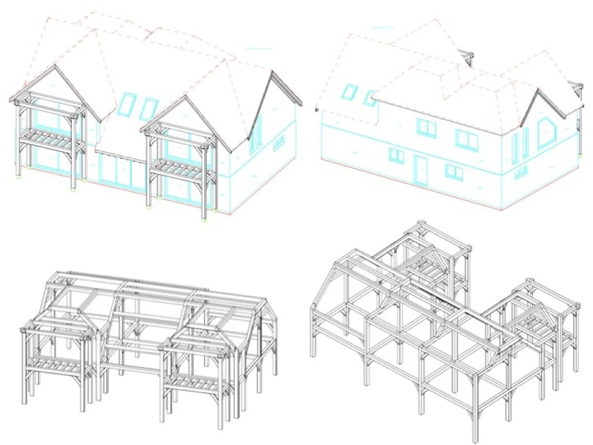
We hadn’t really thought about how the oak frame would be fixed to the reinforced concrete slab and, in a way, we were surprised to see that it was held in place by gravity; it just sits on the slab. But on reflection, and bearing in mind its weight and size, it is unlikely to move.
The diagram on the right shows the different forces exerted by each of the oak posts, from the smallest (30kN) to the largest (100kN). By way of comparison, a 100kN force is equivalent to a weight of 10,197kg.
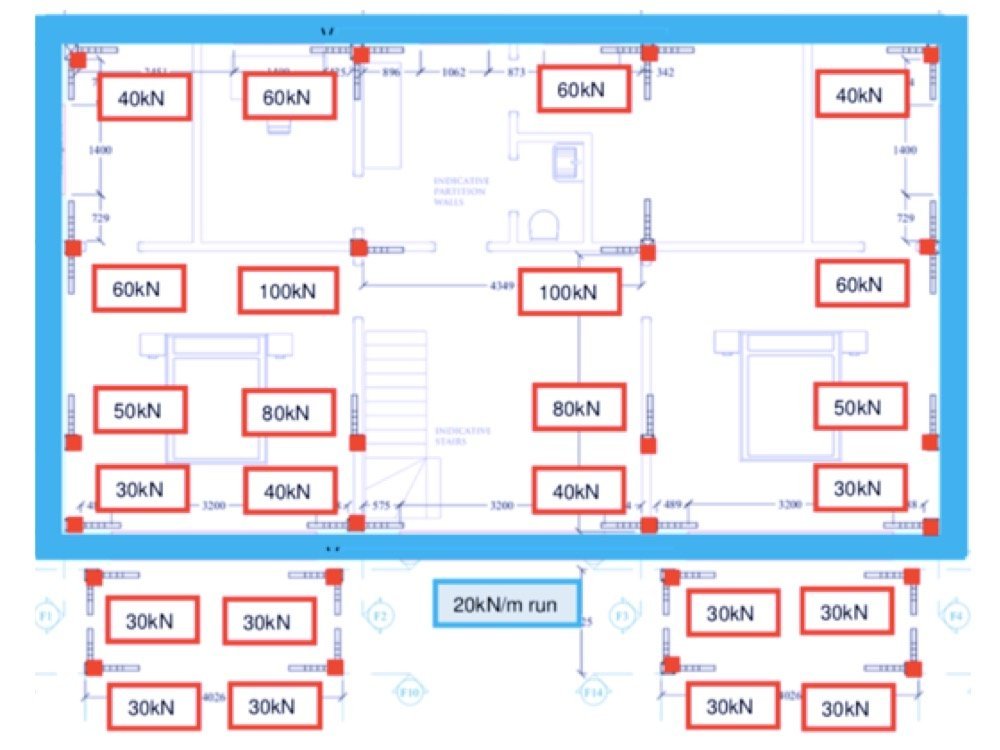
And, as referred to in another post, the concrete slab sitting within the Isoquick ground insulation system was reinforced where each post is placed, thus creating more stability; the reinforcement being designed by a structural engineer working for Isoquick based on the frame’s individual post loadings calculated by Oakwrights.
The picture on the right shows some of the areas of additional reinforcement in the ground slab to support the oak posts.

The oak frame goes up
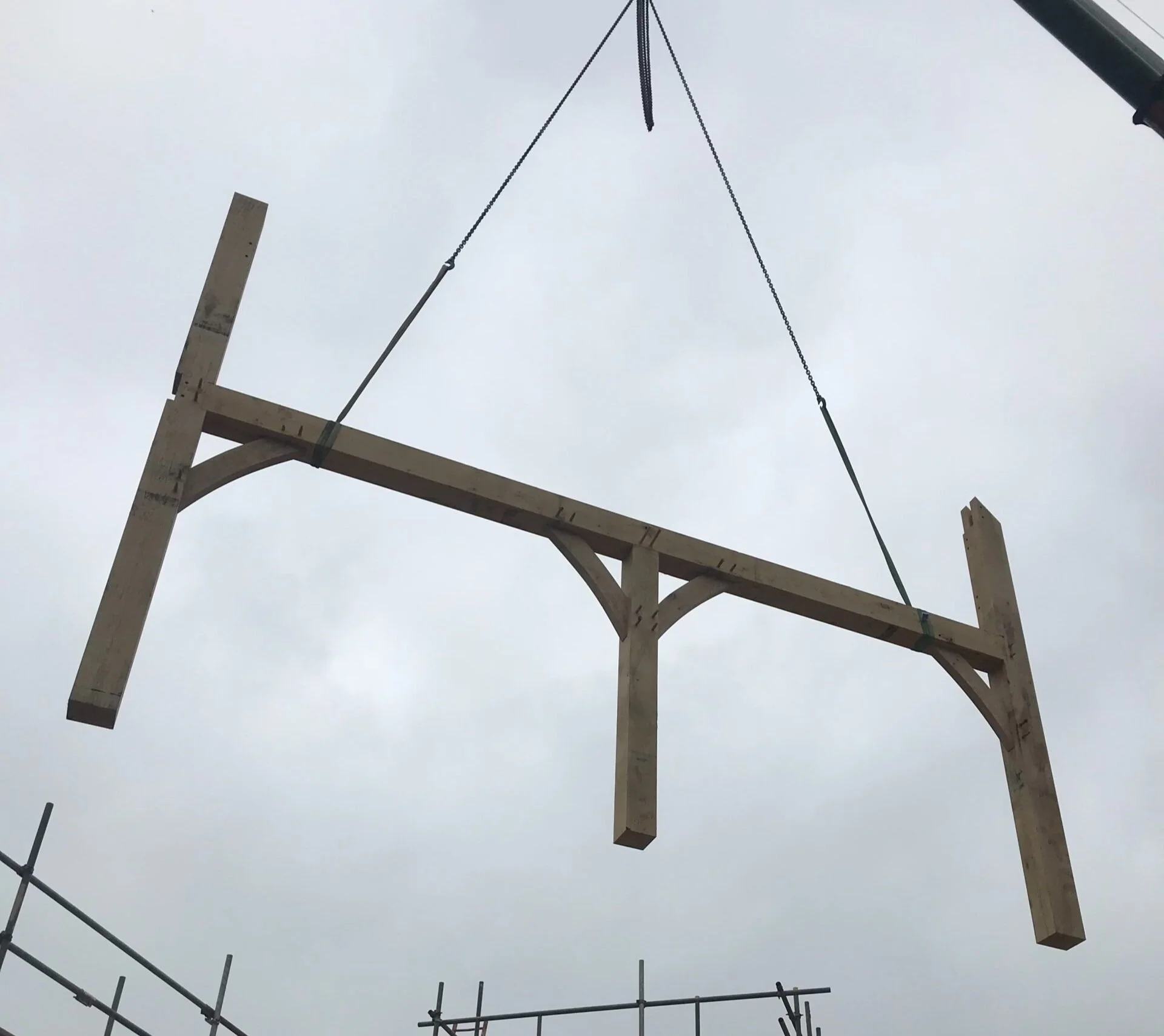
In some ways, raising the oak frame was the project’s most exciting part: we could see our home coming to life instead of just imagining it from drawings. The process was also quick: it took about eight working days to get the frame up. The frame was delivered on the backs of lorries and section-by-section lifted into place by a crane onto the concrete slab.

Some sections of the oak frame were ready-assembled and others were separate. All of the oak frame pieces had been previously ‘dry fitted’ in the Oakwrights factory to ensure that everything went together properly. The picture on the right shows the first section being craned in.
The next video shows the installation of the first parts of our house’s oak frame. The precision of the manufacturing is demonstrated in the relative ease of this task; it’s a bit like putting a giant and very complex piece of flatpack furniture together to create a house frame with the potential to last hundreds of years.
And the video below shows one of the girding rails being installed into our house frame (the picture to its right shows the names of the relevant parts of the frame); the process involves simultaneously joining two posts, the girding rail and two braces.
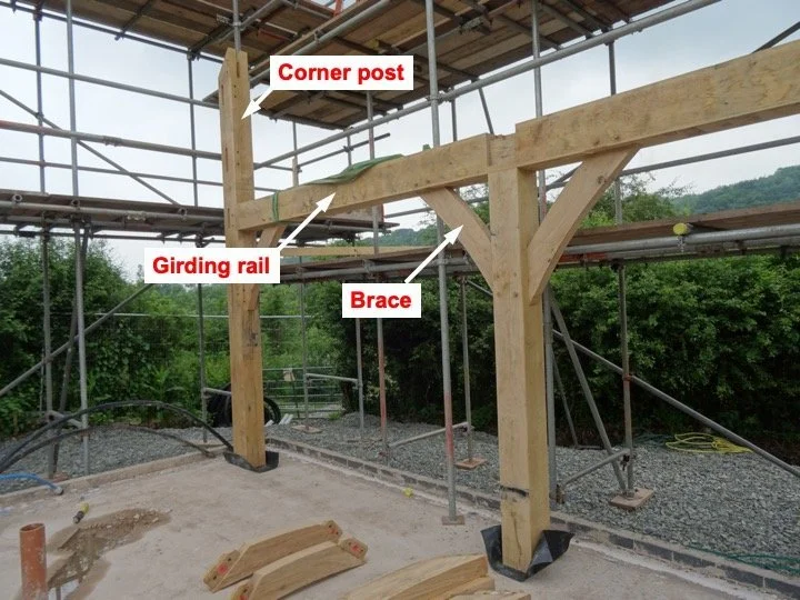
Names of some of the key parts of the oak frame
First-floor joists
The joists and first-floor flooring were also installed by the Oakrights team. Some of the Posi-joists used are shown in the pictures below.
Also shown are some of the upstairs floorboards. These were glued both to each other and to the top edge of the Posi-joists; the yellow adhesive between the boards is visible in the photograph.
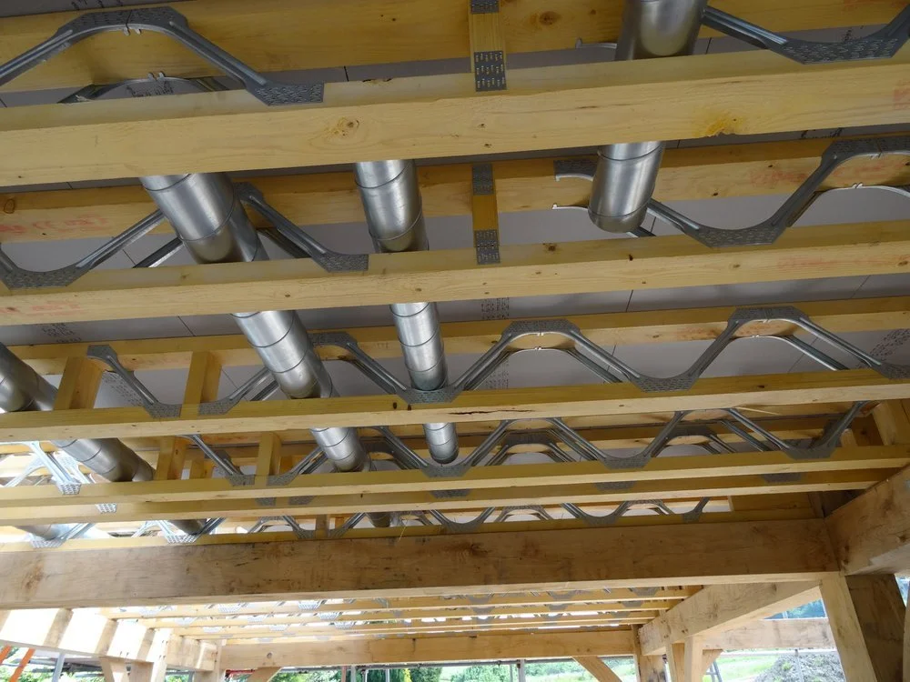
It was important to involve our builder at this stage because some of the rigid steel ducting for the mechanical ventilation heat recovery (MVHR) system had to be installed within the Posi-joist webs, as shown in the picture on the left. Obviously, these had to be fed into the joist webs and the joists were then positioned and fixed. The rest of the MVHR ducting system was constructed later; this is discussed in another post.

Some of the ventilation ducts spanning the Posijoists
Some of the upstairs floorboards
Topping-out ceremony
We considered that holding topping-out ceremony was important: it was an opportunity to celebrate the completion of the oak frame with the Oakwrights team, our builders and our neighbours-to-be. We were pleased to be joined by not just our immediate neighbours but by some from further away, and by the Oakwrights’ managing director.
Traditionally at a topping-out ceremony the house owners provide beer and cake for the builders; and, for an oak-frame house, the youngest member of the construction team fixes an oak branch to the highest part of the frame. We were pleased to be able to do this – with help from a neighbour with an oak tree from which to cut a branch.
Installing the encapsulation system
We have described the Oakwrights Wrightwall Natural structural insulated panel system in another post. We were not directly involved in the design of our encapsulation system as this was determined by the final frame design and the architectural designer’s requirements to achieve the passive house standard.
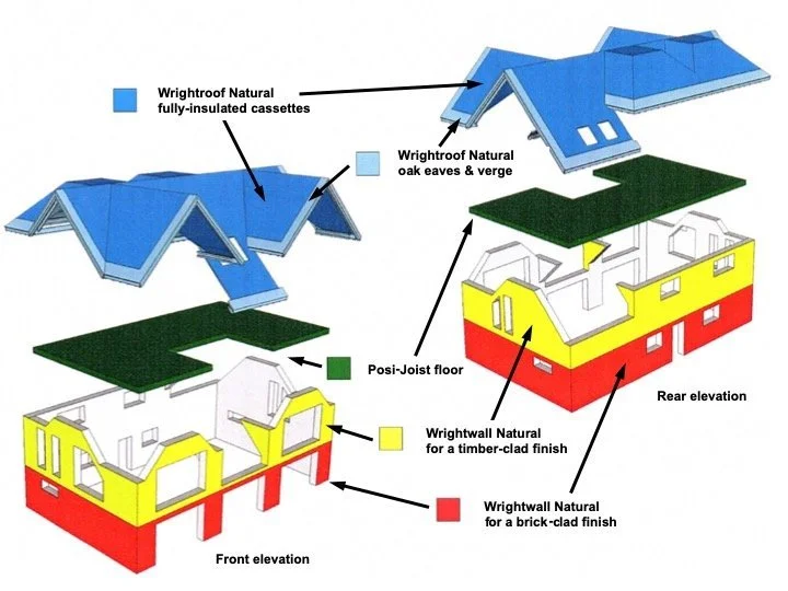
This diagram, adapted from an Oakwrights’ plan for our house, shows the encapsulation system components for the walls and roof and the Posi-Joist flooring for the first floor.
The diagram shows both the front and east elevations (left) and the rear and west ones (right).
Below are some pictures of the insulating encapsulation system being fixed to our oak frame. Put simply, the panels, designed by Oakwrights and made in their factory, were screwed to the outside of the oak frame. Adjoining panel sections were sealed together with adhesive and the joints covered with airtightness tape inside and out.
Like the oak frame, the encapsulation panels were craned into place and fixed to the oak frame using screws some 560mm long; one is shown below the picture on the left.
With the Oakwrights’ encapsulation system side panels are joined to special corner pieces, one of which is shown, top left, in the composite picture below. Use of such corner sections makes it easier to achieve the required level of airtightness.
The base of the panels straddle the concrete slab and the insulating Isoquick upstand – this is visible in the right-hand and bottom-left pictures below. The encapsulation panels were also sealed with airtightness tape to the foundations on each side. This was key to ensuring the integrity of the house’s airtightness and thus the effectiveness of its insulation.
As the windows and doors are fixed within the encapsulation system panels they are not affected by the subsequent inevitable movement and shrinkage of the green oak frame. Glazing directly onto a green oak frame (surface/face-applied fixing) risks the glass breaking (because the oak frame shrinks) unless it is fixed with a special system. However, face-applied fixing may make the achievement of the Passivhaus standard more difficult as the window frame needs to be both draft-free (through sealing with airtightness tape) and, importantly, ideally enveloped in the insulation layer rather than laid onto it, as described in another post. Using a structural insulated panel system such as the Oakwrights one makes this easier to achieve.
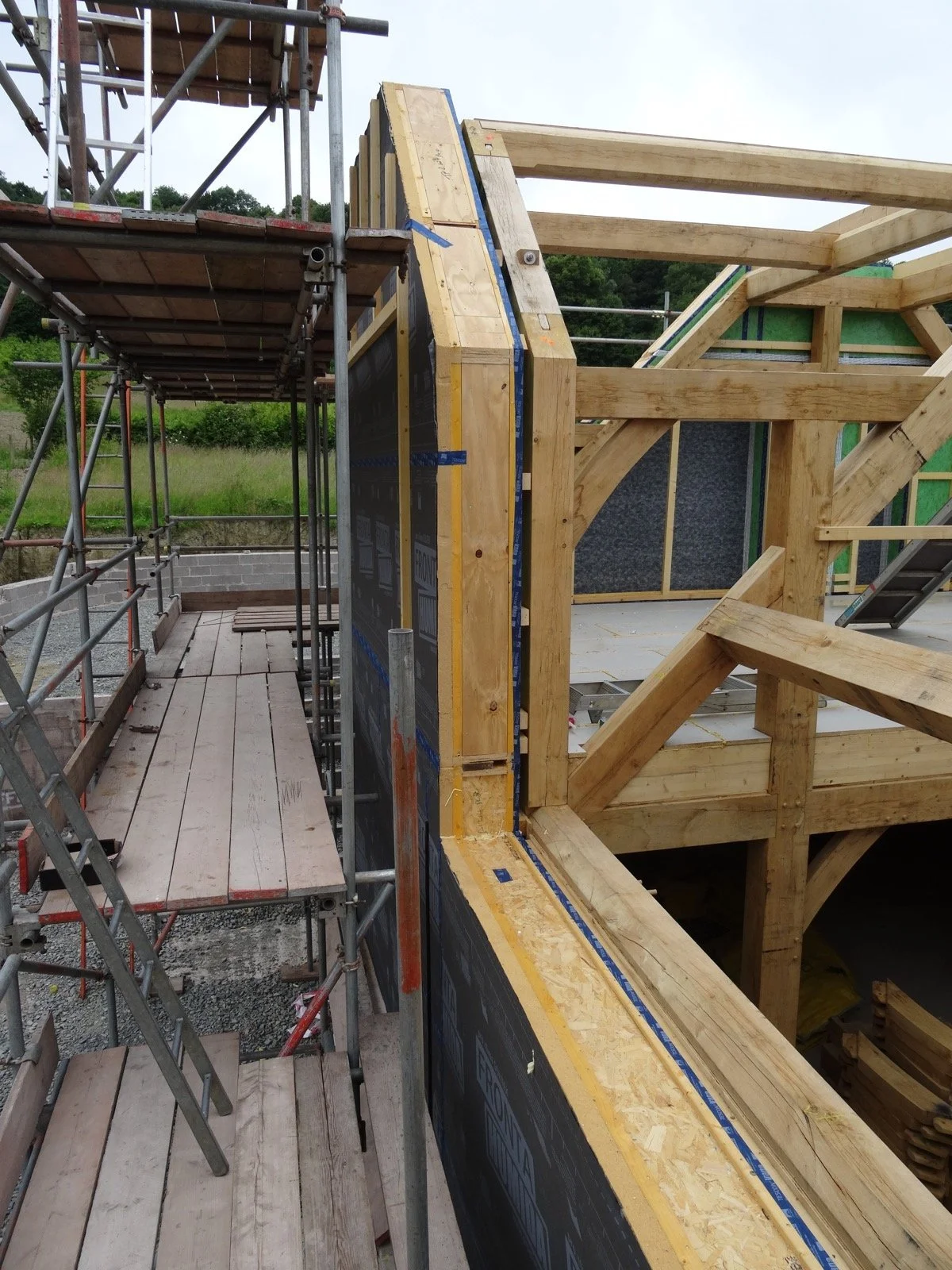
The picture on the right shows the encapsulation system fixed to the upper floor frame at one end of the front of our house. This was subsequently fully enclosed by encapsulation roofing and side panels.
This is further explained below.
In this picture you can also see battens fixed to the inside of the encapsulation panels abutting the oak frame and to which the internal plasterboard sheets are fixed to create a service void, for example, for electrical wiring.
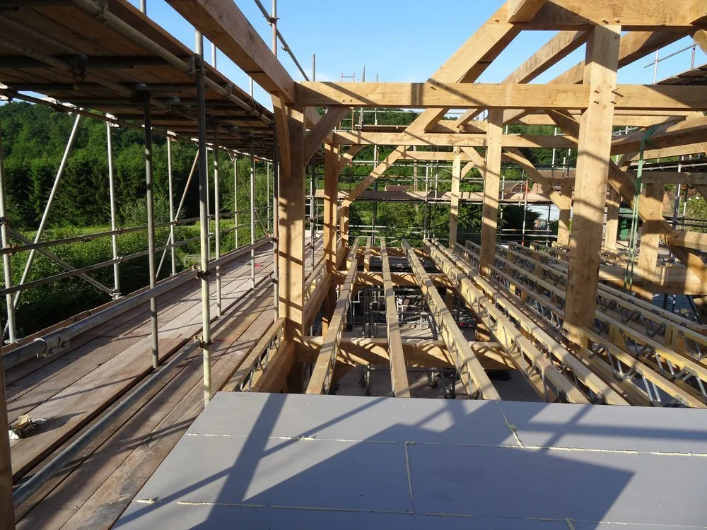
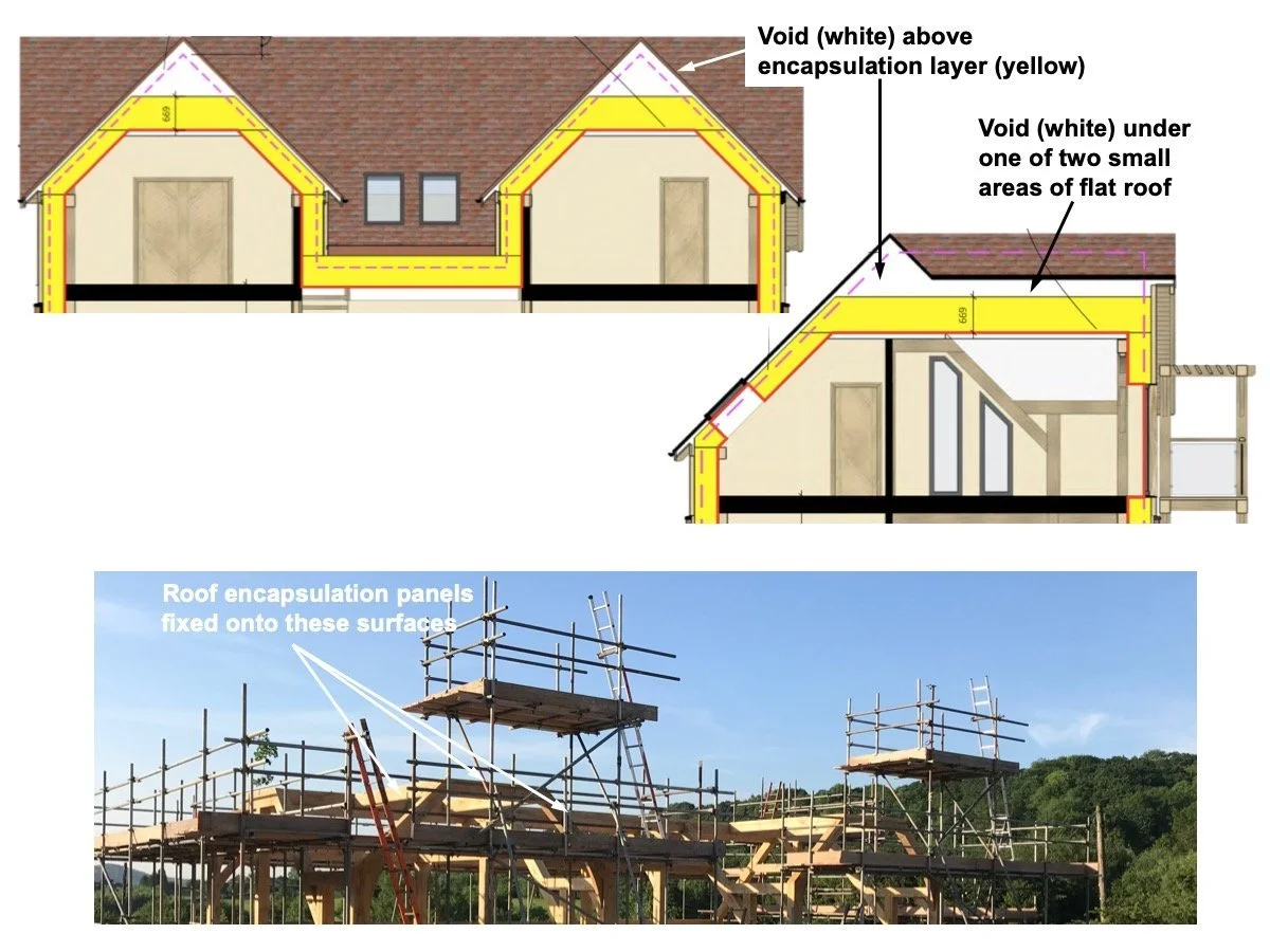
The diagram below is of the upper floor. It shows where the insulating encapsulation panels are fitted to the oak frame to cover the house. The left-hand gable end of the front of the house in the diagram below is the one shown in the photograph above. Both front gable ends are shown behind the scaffolding in the photograph below the diagram.
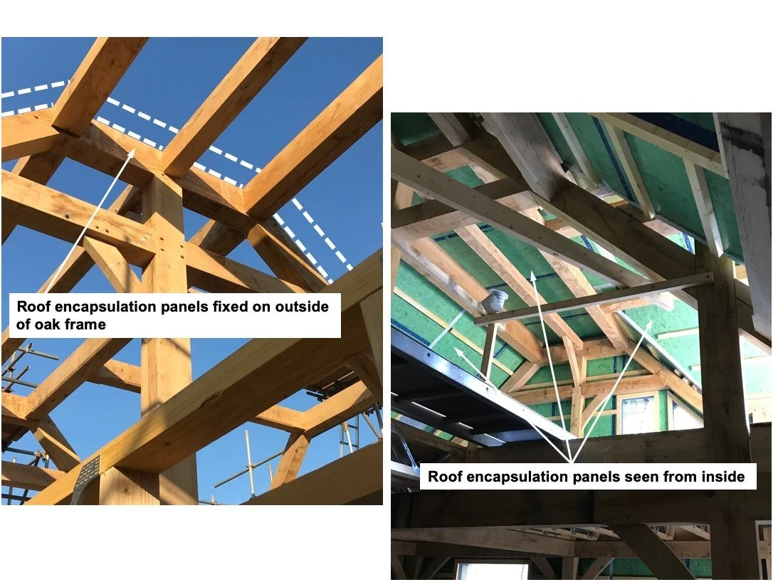
The pictures on the right show parts of the roof from inside, again showing where the insulating encapsulation panels have been fitted to the oak frame (depicted on the left by the white dashed line); the green panelling on the right is the inner face of the encapsulation system itself forming the airtightness layer.
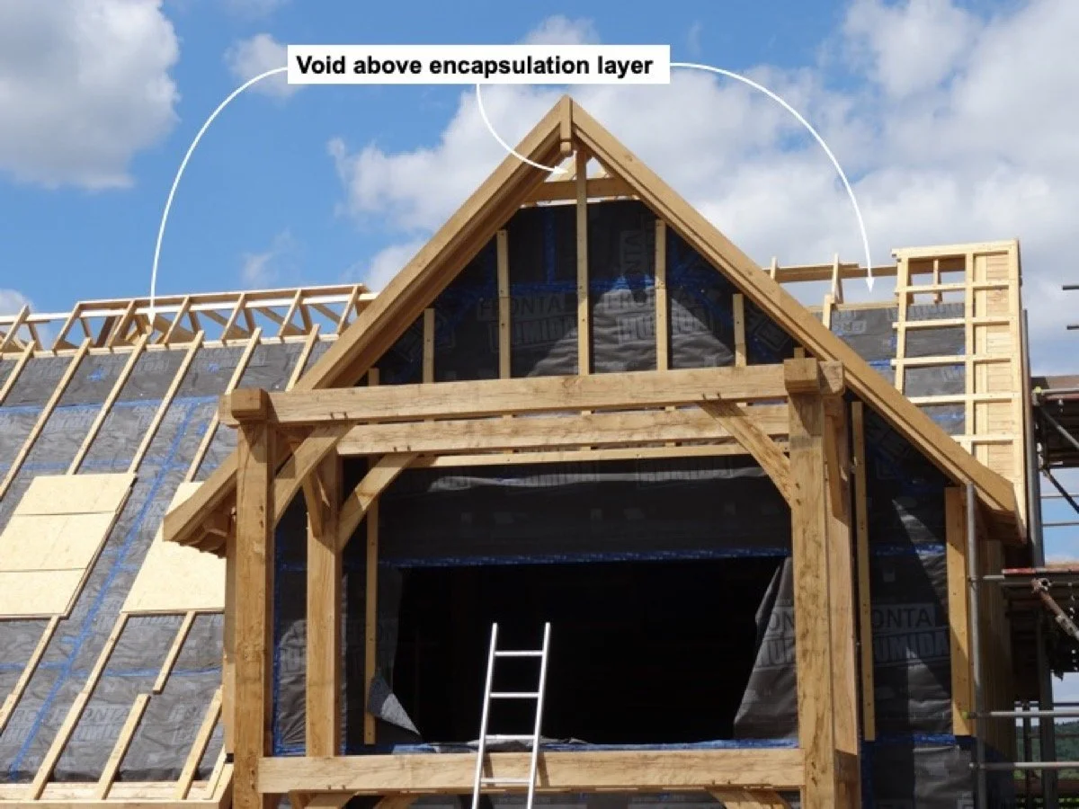
As shown in the diagram above and the picture on the right, the encapsulation system did not extend to the very top of the roof gable thus enabling the internal house volume to be compatible with the Passivhaus heating standard. This aspect is described in another post. Thus, in order for the external appearance to show traditional gable ends, it was necessary to extend the roof above the encapsulation system thereby creating a small void above it. Because this void is outside the encapsulation system it forms a small area of ‘cold roof’.
Our house also has two small areas of flat roof at the back to avoid a too-high roof ridge (shown in the diagrams in oak frame design section of this post, above). These are also ‘cold’ roofs. A cold roof is created when the house’s upper insulating layer is below part (or all) of the roof. This means that there is a risk of condensation in these voids principally from the outside air rather than water vapour rising from the house. The roof under the tiles is thus lined with a permeable membrane to let water vapour out. We also asked our builder to install air vents in the gable ends, the mid section of the main roof, and in the flat roof areas to keep these vented to prevent condensation from damaging the roof materials internally.
There are various articles on cold roofing on the internet, but these mostly refer to flat roofs and to more conventional construction with rafters. Whilst the risks of condensation and the desirability of using effective breather membranes and/or ventilation apply to the void (cold) areas in a roof such as ours, the bulk of the roof area is part of the living space upstairs and is ‘warm’ because it is within the insulating encapsulation system.
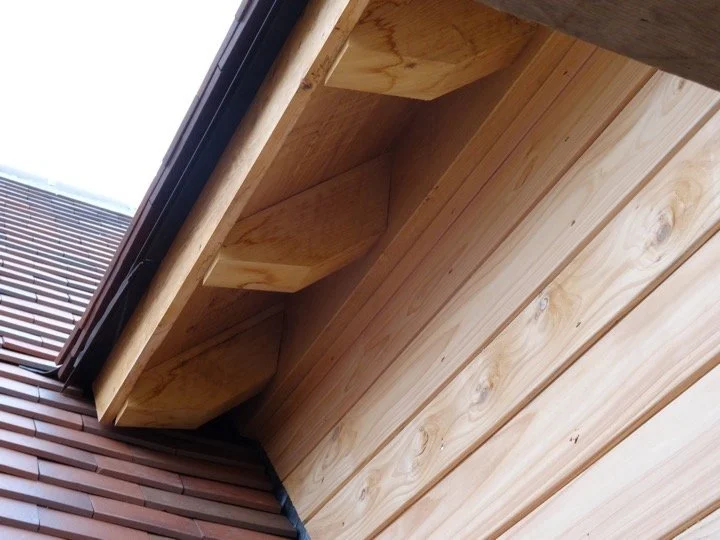
Also visible in the picture above is the Oakwrights’ gable end structure. The eves, soffit and facia components of this (the Wrightroof Natural oak eves and verge) are shown in the picture below (which is of a different part of our roof).
In a traditional oak-frame house the eves would be a continuation of the roof rafters and be closed-off by the soffit and facia boards. In the Oakwrights system, this part of the structure is fixed outside the encapsulation system and is not part of the building’s structure. It gives the appearance of being part of a traditional roof structure but, by being structurally disconnected from it, does not create a cold bridge and thus maintains the integrity of both the insulation layer and the airtightness layer. This is shown in the pictures below.